Arduino Projects - 2020
September to December
Time on My Hands
The Clock Section
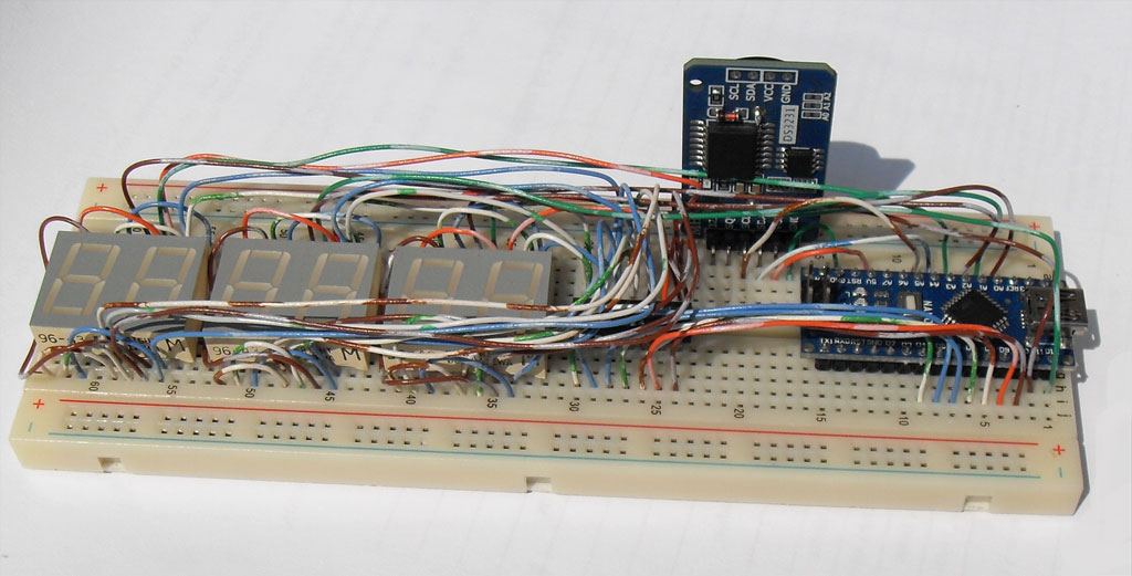
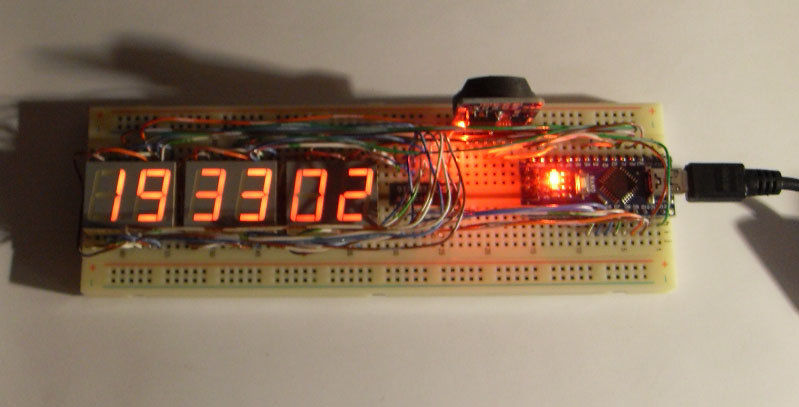
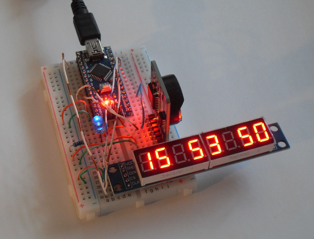
The board mounted vertically is a DS3231 battery-backed clock module. The microprocessor at the top formats the time data for the display.
A 1 Hz interrupt from the clock module times the data read.
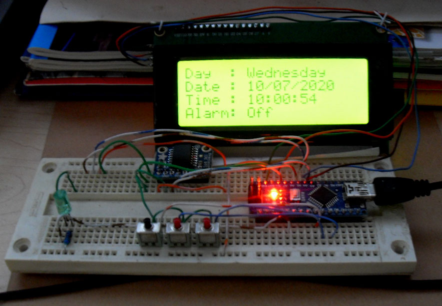
The display is driven with an IIC/I2C interface that requires only SCL and SCA inputs.
Frequency Synthesizer
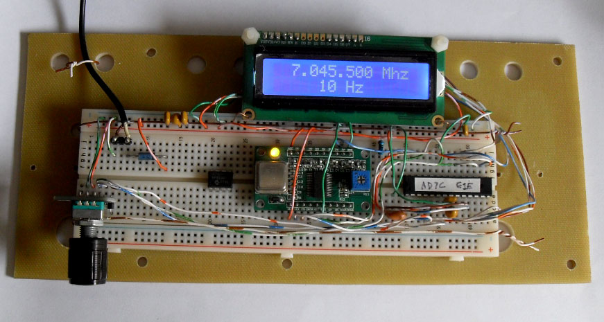
The code initially running in the Nano has been moved to a single ATmega328p chip.
Thermometer
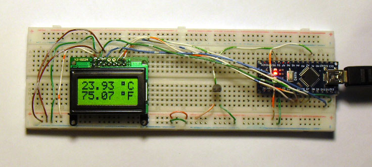
The 10-bit Analog to Digital converter in the Nano microprocessor gives what appears to be a very
precise reading, but the step-size is almost 0.8 degrees Celsius.
Outdoor Temperature and Humidity
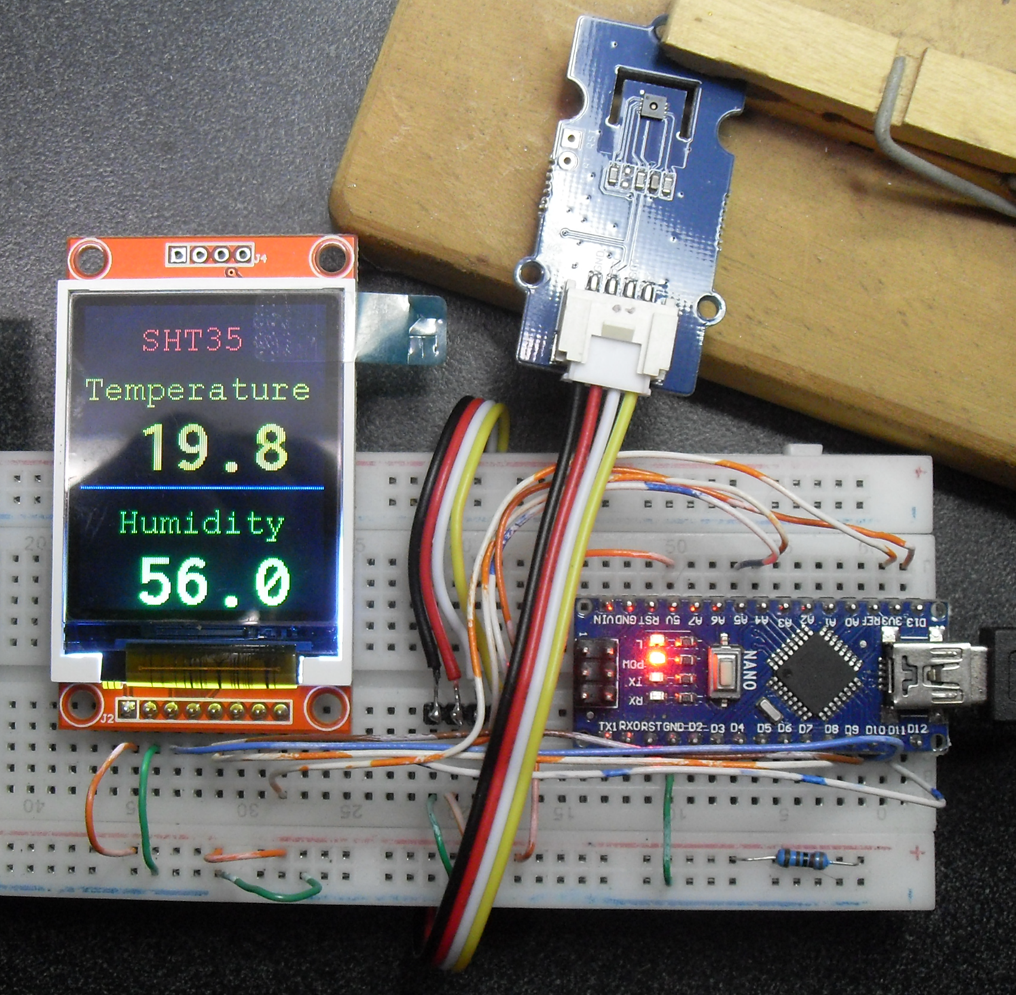
It's the tiny black square on the blue circuit board held by the clothes-pin.
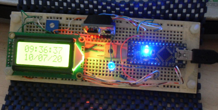
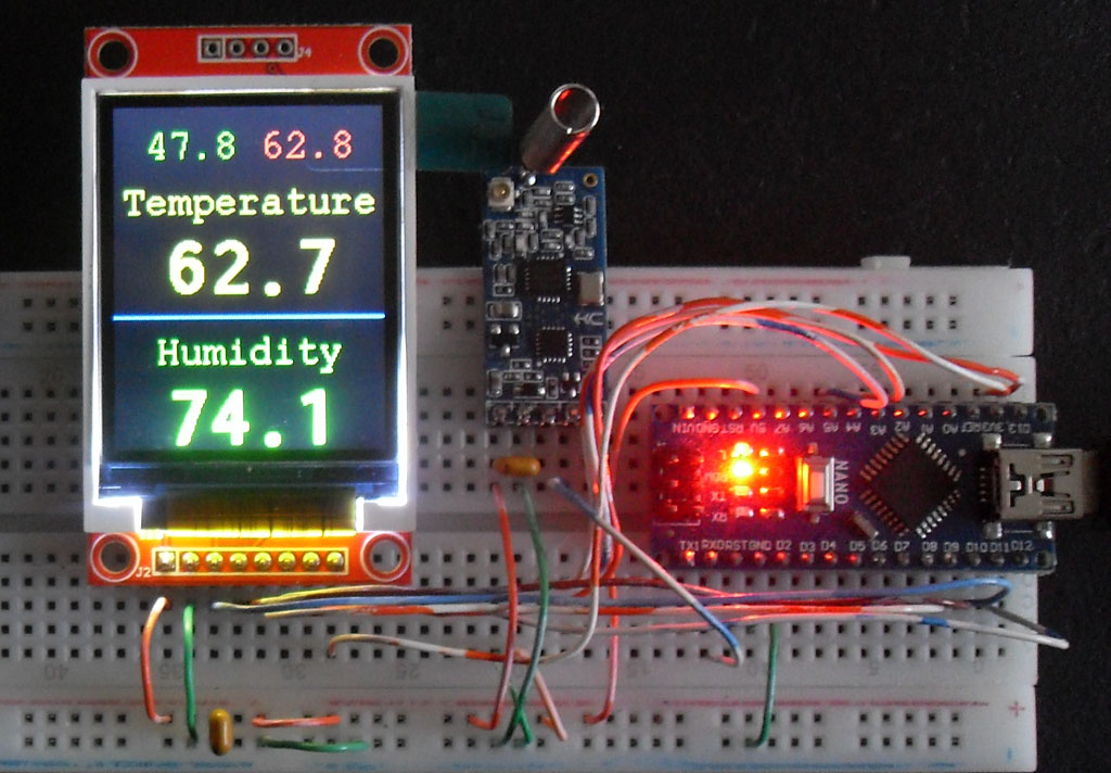
My first cut fed the data to an 8-digit, 2-line monochrome LCD. I upgraded the display to a 1.8-inch 128x160 pixel color OLED
display that was uncovered in an archeological dig in the garage.
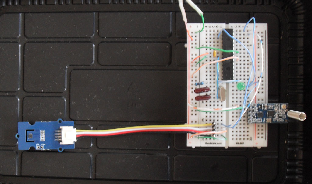
The transceiver is the module with the spring antenna. It sits idle until TTL level serial data is fed in.
The transmitted data format uses starting and ending symbols ( "<" and ">") and puts the comma-separated temp and humidity values in between.
Software in the Nano has a function that inspects the incoming serial stream and starts saving the data in an array when the "<" is found and stops when the ">" is found.
Another Arduino library function separates the values in the array by looking for the "comma" separator.
That made parsing the data to display a lot easier than I expected it to be.
The top line displays the low and high temperature since the last reset.
Data Logger
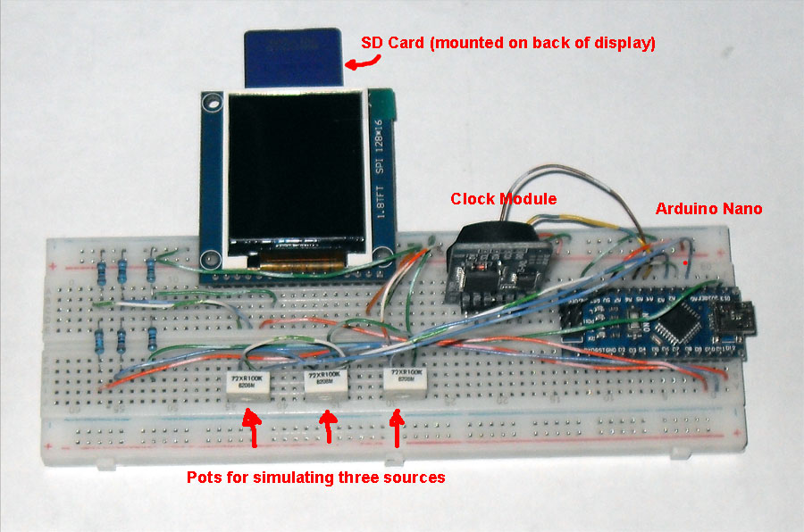
Power consumption is 20 mA at 5 volts.
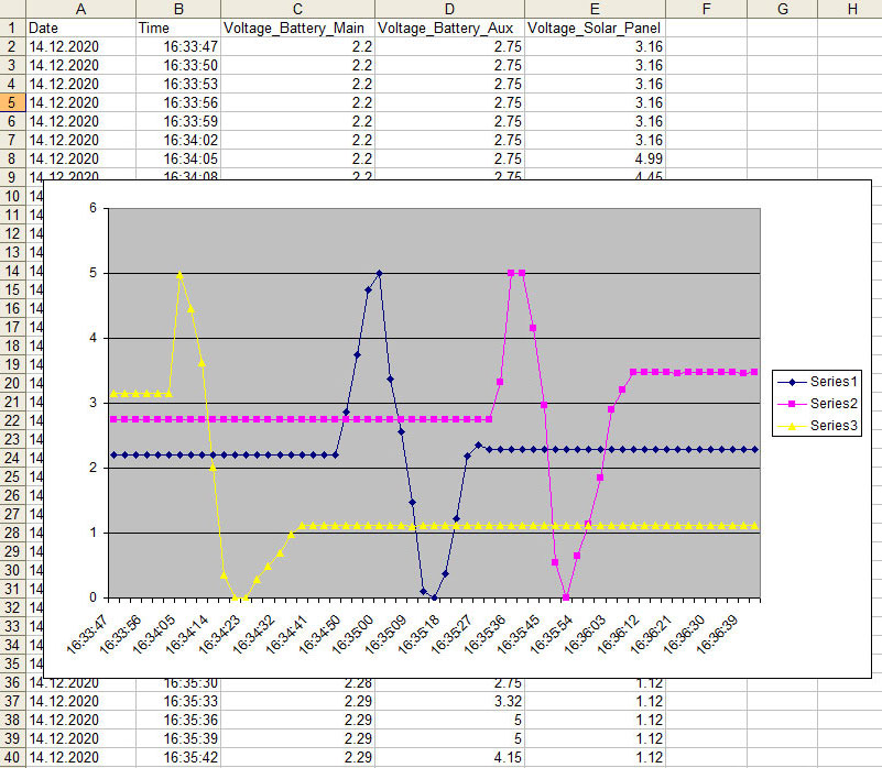
The data range shown here is zero to 5 volts on each channel.
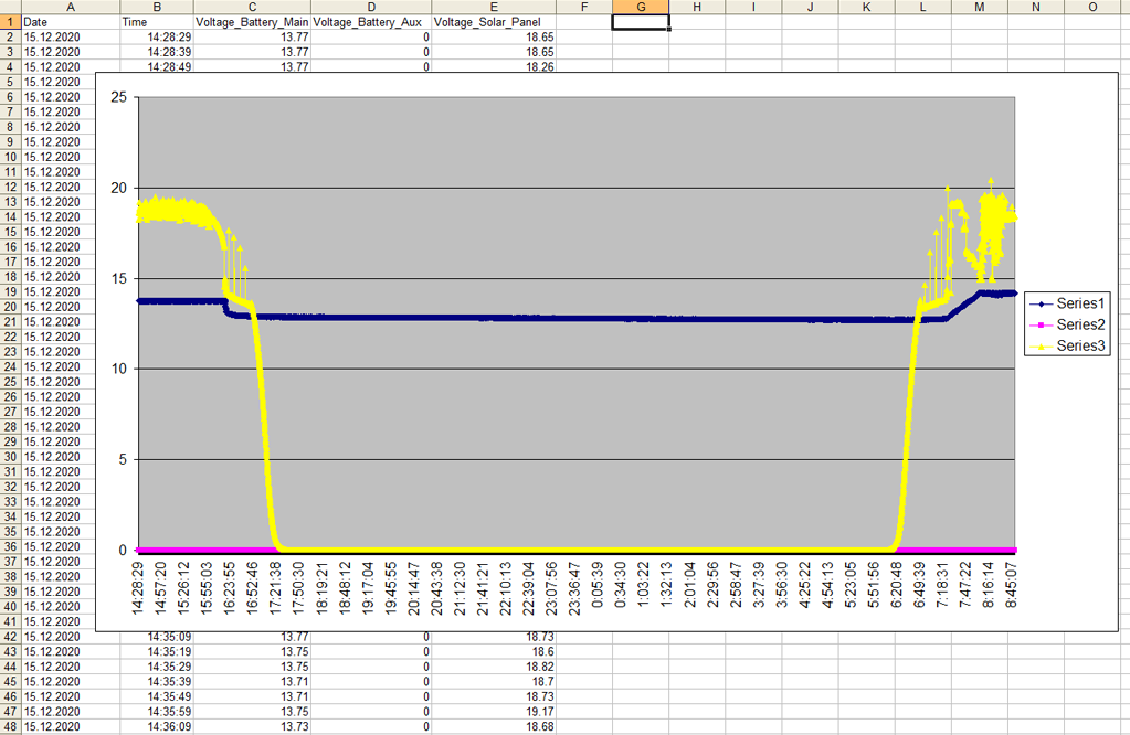
Yellow trace is the solar panel voltage from 2:28 PM, through the night, until 8:45 AM the next morning.
Blue trace is the battery voltage, dipping slighty at night, and being recharged after sunrise.
Magenta trace, reading zero, is a disconnected channel.